Types of Tube Fittings: Learn the Key Differences
Your Guide to Choosing the Right Small-Bore Fittings
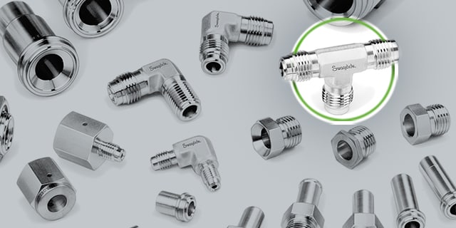
There are a variety of types of fittings to choose from, however, and it may not always be clear which is the best choice when you’re performing maintenance on an existing system or building a new one.
How should you choose the right fitting for your needs? Let’s investigate several common fitting types along with their specific characteristics and advantages:
Threaded Fittings
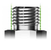
Threaded fittings come in two distinct varieties: those with straight or parallel threads, and those with tapered threads. Straight threads are designed to hold a nut onto the body of a tube fitting and rely on supplemental items, including gaskets, O-rings, or metal-to-metal contact to create a leak-tight seal. For this reason, straight threads are typically used in applications where system pressure will not exceed 5000 psi.
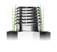

Straight threads are typically used when system pressure will not exceed 5000 psi. Tapered threads are effective for system pressures up to 15000 psi.
Aside from the noted system pressure limits, the choice between straight or tapered threaded connections is often guided by user preference. Generally, available threaded fittings adhere to common standards; British Standard Pipe (BSP) and the National Pipe Thread (NPT) are two of the most common. It can be beneficial, though, to standardize the use of one type versus the other throughout a facility to reduce potential confusion or misapplication.
Compression Tube Fittings
In contrast to threaded fittings, compression tube fittings commonly utilize ferrules to create a leak-tight seal. When the fitting’s nut is tightened, the ferrule is compressed between the nut and the receiving fitting. As a result of this compression, the ferrule effectively bites into the tube, thus creating a strong grip and a tight seal. The reliability of the tube grip is related to how well the gripping ferrule performs this function. Compression fittings also offer the benefit of being simple to assemble and disassemble.

Compression fittings that feature a two-ferrule design can improve grip strength and seal performance.
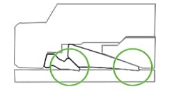
There exist some key design differences among the variety of compression tube fittings commonly available today. A bite-type ferrule, as illustrated here in both a single- and double-ferrule design, bows when assembly occurs. This bowing action drives the leading edge of the biting ferrule into the tube to grip or indent the tube surface. The leading edge of these bite-type ferrules is intended to bite for proper tube grip. If there is vibration, pulsation, thermal shock, or side load exerted on the fitting, the minimal contact of the gripping ferrule offers little support behind the bite. This means in a dynamic system, the potential for either damage to the tube or pullout may exist.
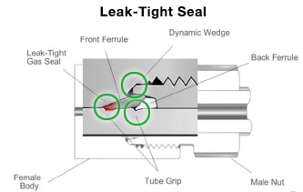
Compression fittings that feature a two-ferrule design can improve grip strength and seal performance. Here, a gas seal is created between the front ferrule and the outside diameter of the tubing, as well as between the seal surface of the body. The back ferrule also acts as a primary mechanism to secure the tubing in the fitting. During installation, the back ferrule axially advances the front ferrule and radially applies an effective tube grip.

 Medium-Pressure Tube Fittings
Medium-pressure mechanical grip fittings—an evolution of two-ferrule compression fittings—also deliver outstanding performance along with enhanced installation efficiency.
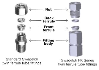
Swagelok® FK series fittings provide a good example of how mechanical grip technology differs from compression-style fittings. Using similar hinging-colleting action to a standard Swagelok® two-ferrule tube fitting shown here, the FK series differs by utilizing a female fitting body, a male nut, and pre-oriented ferrules. This design creates a unique dynamic wedge. The dynamic wedge allows for remakeable pullups by torque and provides gaugeability at initial assembly and remake of the tube fitting. The two-ferrule design creates a more robust bite into the tubing, creating a leak-tight gas seal upon initial installation and every remake.
 Cone and Thread Fittings
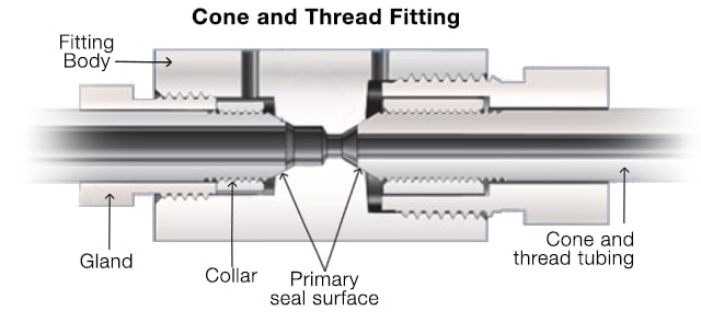
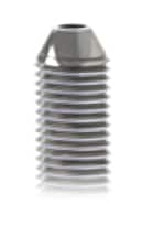
Finally, cone and thread fittings are available in a wide variety of alloys and have several design features that make them suitable for medium- to high-pressure applications. Their reliable performance has made them a standard high-pressure fitting choice in a variety of demanding applications for many years.
Cone- and thread-specific tubing, featuring thicker walls and a higher pressure rating, is typically required when cone and thread fittings will be used. A high-performance cone and thread fitting will feature a gland, a collar, a female port, and a weep hole that enables you to detect leaks and verify proper installation.
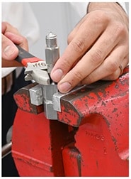
Special care must be taken when preparing and installing cone and thread fittings. Coning and threading tools are required to make the connection, along with lubricant to reduce friction during the cutting process. The tube must be properly coned and threaded before being joined with the fitting. It’s critical to ensure that no burrs, gouges, or scratches have occurred during the process. Once the tubing prep is complete, a collar is threaded onto the tubing and a gland nut is inserted into the fitting body for final tightening. For systems that experience regular shock or vibration, it is also recommended to use anti-vibration components to help extend the life of the tubing connection. If assembled properly, cone and thread fittings can provide reliable long-term performance in some of the most strenuous fluid system applications.
***
Having learned some of the key differentiators among the variety of fitting technologies available today, you will be better equipped to make the right choice for your fluid system applications. However, this article only covers the basics of small-bore fittings—there are many other complexities involved with tube fitting selection and installation.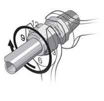
If you’re interested in further developing your understanding of the world of small-bore tube fittings, check out Swagelok's in-depth training opportunities. Our training programs provide valuable and practical tools for meeting day-to-day challenges related to fluid system design, operation, and maintenance. Through these in-depth, hands-on courses taught by experienced instructors, both new team members and industry veterans can find the information needed to master tube fitting selection, installation, inspection, and troubleshooting—among other fluid system topics. Learn more about available offerings at the link below.
Related Fittings Articles
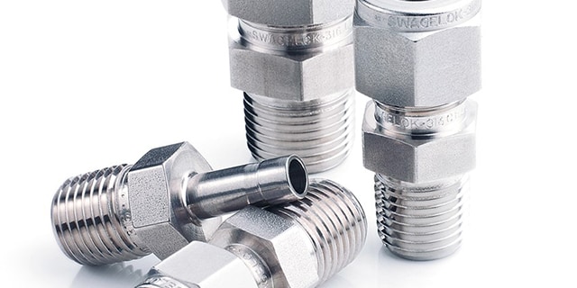
An Introduction to Fittings: Identifying Thread Size and Pitch
Learn how to determine thread size and pitch for fittings in your small-bore industrial fluid system using the right tools, decreasing the chance of leaks or blowouts.
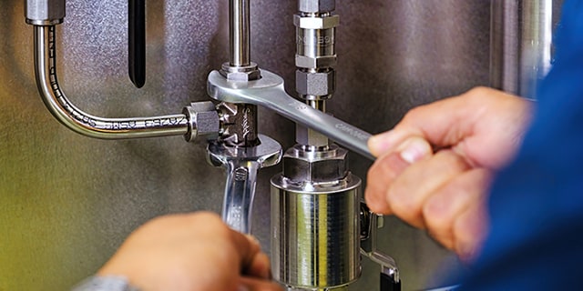
Why You Should Not Intermix Tube Fittings
Learn why intermixing or interchanging tube fitting components from different manufacturers can lead to poor fluid system performance.
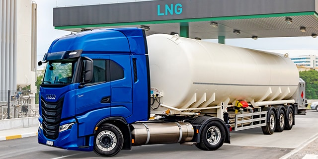
Specifying High Performance CNG/LNG Fittings
Compressed natural gas (CNG) and liquefied natural gas (LNG) transportation applications require high-performance tube fittings that meet a number of important criteria. Learn what makes for an ideal CNG fitting or LNG fitting.


